There is more than one way to do overhead transmission
About 10,000 km of very largely above ground transmission are to be built in the NEM in the next decade representing at last pubished cost estimates over $40 bn of investment. As such its a great time to be talking about how above ground transmission can be best done from every perspective. In this note we look at four ideas, Dynamic Line Ratings, Advanced conductors, painting towers, and monopoles.
Disclaimer: This is the first time for me at looking at overhead transmission “technology” choices. Also I am a financial analyst (a generalist) rather than having any technical electrical engineering training. As such its very likely that I wont properly understand the tradeoffs in overhead transmission. That said my deep background as a rated analyst gives me experience in the process of “evaluating pitch decks”.
Is it just above ground v underground?
New residential subdivisions mostly have the residential services put underground, that includes electricity, water, gas and cable. AC electricity doesn’t do well underground but it works well enough for the short residential distances. When it comes to higher voltage transmission the story is different.
In Australia virtually all transmission is built above ground. The reasons for this were fairly comprehensively explored in two NSW upper house committee enquiries into Humelink. In short it mostly comes down to time, cost and that underground needs to be DC in order (i have read) to avoid “capacitance” issues. Even when you ignore cost and time my reading of the Humelink enquiry submissions was that even the environmental tradeoffs are not that obviously favouring underground.
If above ground is in fact the reasonable choice for transmission then the next question is can it be done better? Here I would observe that for various reasons relatively little transmission has actually been built in the NEM over the last 20 years. Energyconnect is now under construction and before that there was a rebuilding of Southern QLD transmission partly to support the CSG electrification. No doubt there are other works, typically enhancements of existing circuits. Certainly though we haven’t had the widespread build that is now required.
Another factor that goes into this is the nature of landownership where the crown retains the right to build transmission after compensating the land “owner”. Its been well observed that this is a power imbalance but my concern here is to observe that few land owners know much, if anything about the technical side of transmission, and few landowners have much formal environmental training. And I am in the same boat, just with time to read and know some people to talk to.
So for both the engineers and the communities this is a new experience. All parties will eventually get better at it as we moved down a transmission development learning curve.
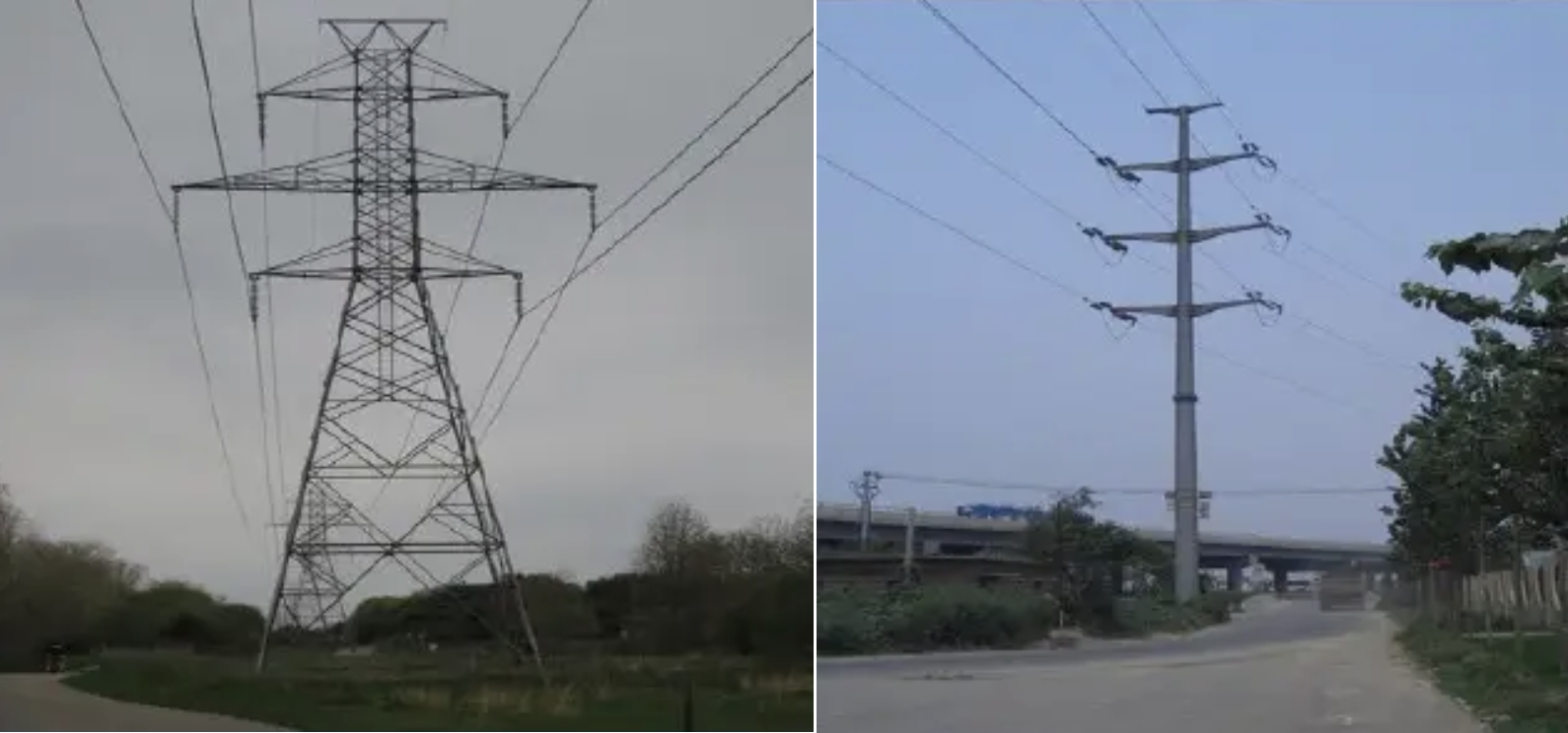
Idea one: Monopoles instead of Lattice
The following section is taken directly from XYtowers.com although it was in reading some USA literature that I first saw monopoles:
Lattice v Monopole: Source SCRIBD (lalit23india)
Monopoles
Smallest footprint of all tower types.
Can be used for installations from 9 to 45 m.
Generally considered the most aesthetically pleasing structure,
Significant wind–loading capacity.
Requires crane for installation.
Higher freight costs because a full flatbed is required for delivery
More expensive than Lattice for various reasons including more concrete in foundation, but significantly faster assembly time and generally if crane access available lower installation cost.
Antennas are usually mounted on a monopole with a vertical separation of 3 m to 4.5 m increments.
High quality connection: Reliability and high quality of signal reception provides rigidity and resistance to external influences, especially in difficult icing and wind conditions.
Compact: The base support size allows the support of a small area of building, which is particularly important in the construction in the city.
Aesthetics: Exterior construction favorably differs from traditional designs, which is an important factor in the placement of towers in the city, on the territory of enterprises, protected areas, etc.
Operation: Placement of the equipment, cables, feeders, maintenance of stairs inside the support eliminates unauthorized access to equipment, provides weather protection, i.e., increase the service life, it allows you to carry out work in difficult climatic conditions and the result of drastically reducing operating costs.
Flexibility in design.
Self-supporting lattice tower
Can be used for installations from 6 to 60 m.
Often ships knocked down, reducing freight expenses but requiring on–site assembly
Significant wind–loading capacity.
Can accommodate heavy loading of antennas and microwave dishes.
Less cost than Monopole.
Ecological: The lattice structure is highly transparent so that it has a lesser effect on the landscape. Optimum ecological balance thanks to the galvanized steel structure and small concrete foundations (savings in terms of raw materials; both tower and foundations can be recycled)
Idea no 2. “Camo”
If there is one thing that excites the rural types (and I am one) its supporting the military and using their ideas, one of which is camouflage. Of course pilots might not be happy if the transmission wires and poles aren’t visible but most of the community would be.
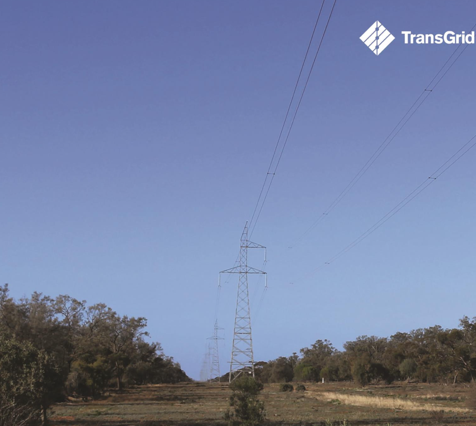
In this case camouflage can be as simple as painting (powdercoating) the towers. I am indebted to a reader who sent me (1) the process that Transgrid went through for the NSW section of EnergyConnect looking at the visual impact. If you read the summary of this Technical Paper you would see:
Considering the length and scale of this proposal, the visual impacts are relatively low and have a relatively small influence. Those visual impacts which have been identified mostly having a low to moderate visual impact…….. Any cumulative visual impact would be experienced from a small area and therw would be an opportunity to reduce the visual impacts of the respective project through the implementation of screening vegetation.
Energyconnect NSW. Source: Transgrid
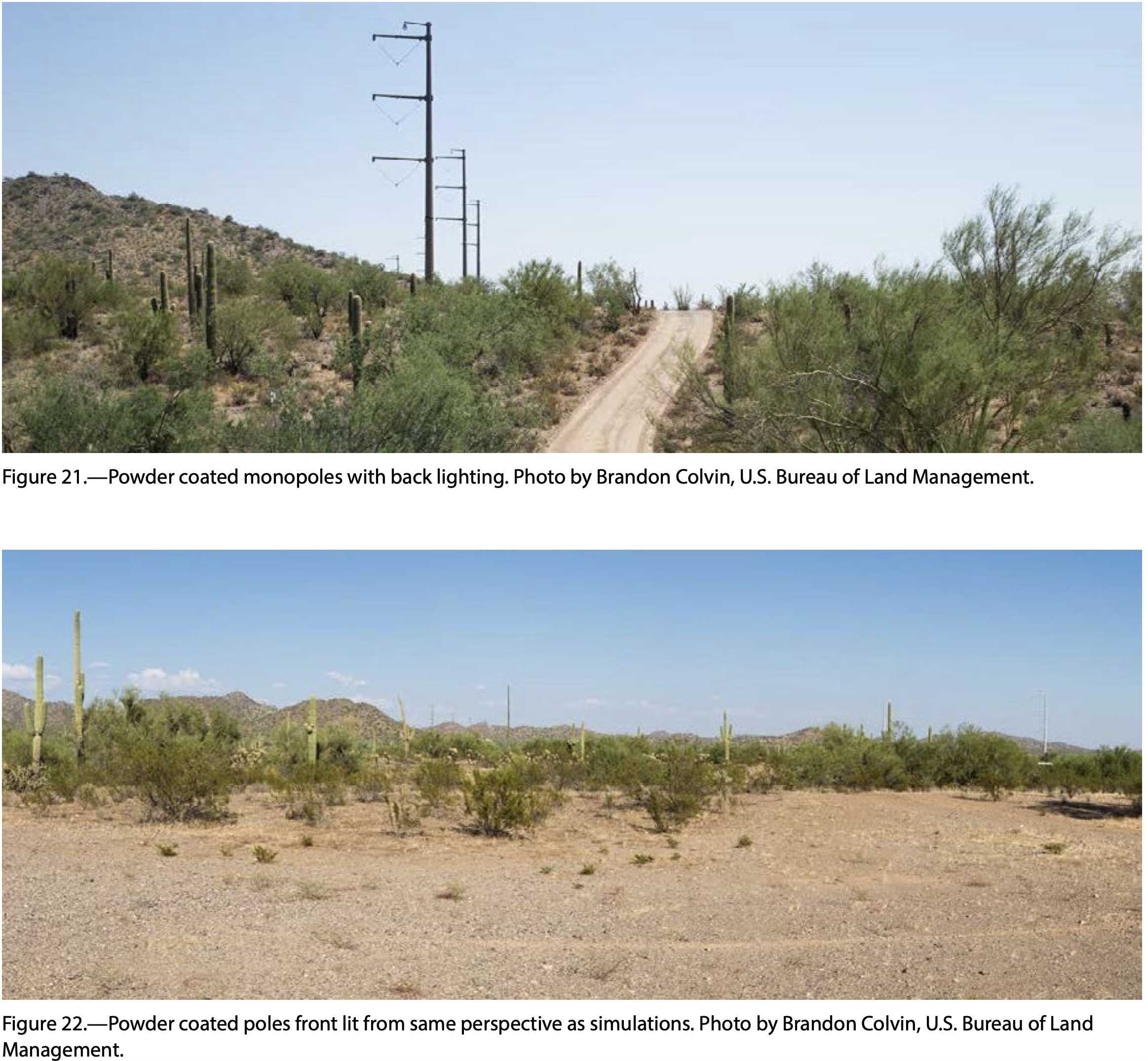
In contrast to the “no problem and grow a few shrubs” approach of Transgrid, was the approach adopted by Brandon Collin, Landscape Architect at the USA Bureau of Land Management for 38 miles of 500 KV transmission Sun Valley to Morgan in Arizona. If you have the time its a good and easy read.
Color selection was a key part of the visual resource analysis in the EIS for the SV2M project. An in-depth analysis of the existing landscape was conducted to determine the most appropriate color for transmission structures (165-foot steel monopoles) on BLM land. Where the project was proposed, vegetation was dense and the topography was varied. These factors played into the decision to require project elements like poles to be painted in BLM standard colors that have been analyzed in various landscapes and have proven to blend well, especially in vegetated desert conditions
Painted monopoles. Source: Colvin
In Figure 22 you can see a galvanised unpainted pole clearly to the right of the image but need to look harder to see the painted poles in the centre of the photo. Of course with backlighting everything stands out.
Its not just that the results of this process make a difference to the visual amenities. Just as important is observe the difference that a determined landscape architect could make. The transmission company had to fit in because the BLM controlled the land.
The learning I take from this is not necessarily that monopoles are better, or that painting the poles would fix all the visual amenity issues. The learning I take is that Transgrid and every other transmission company in Australia can try a lot harder to give impacted landowners more of what they want. In some cases this may mean rerouting the transmission (generally this is both costly and time consuming) but in other cases it may be that othe approaches offer a lot of benefits.
Idea no 3 - The high tech solution
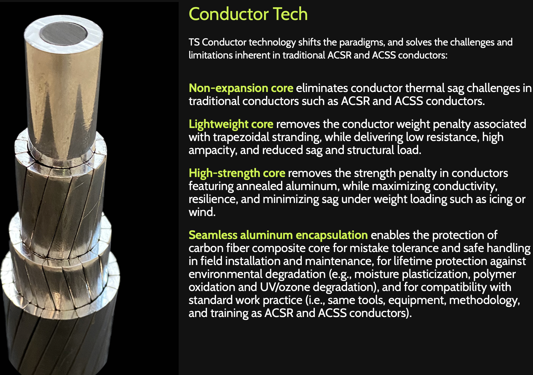
TS conductor: Source: TS Conductor
Rachel Williamson wrote about new conductors recently for Reneweconomy. Rachel referenced an RMI study into Grid Enhancing Technologies. One of those was Dynamic Line Ratings. Powerlink in QLD is already going down this track. Paul Simshauser, CEO, explained how REZ’s can benefit from dynamic line ratings. Its a good read.
An even bigger idea is advanced conductors. Accordidng to the no doubt ambitious claims of TS Conductor these have the potential to roughly halve the number of transmission towers by reducing line sag, offer up to 3X more capacity during peak generation, and reduce line losses by 50%. TS’s product uses a core of carbon fibre ecased in seamless aluminium. Apparently the current technology since the 1970s is aluminium conductor and steel either reinforcing or supporting.
The carbon fibre is strong, lightweight and has little to no sag and the aluminium sheath prevents corrosion. Who am I to evaluate this. You can read an article by Charles Bayless, a Director of TS, at Public Utilities Fortnightly Bayless is talking the book but he has a very good background and I take what he writes seriously. He writes:
TS has gained the backing of respected utility names such as National Grid Partners and NextEra Energy, plus it was admitted to Dominion’s Energy Innovation Center. Earlier this year, TS also won a 2023 Stage 2 CABLE Conductor Manufacturing Prize from the U.S. Department of Energy American Made Challenge.
However this technlogy is yet to be deployed at scale. Bayless continues:
Consider Tennessee Valley Authority, the largest public utility in the country, serving roughly ten million customers. Transmission line systems engineering & design lead Jeff Phillips and the TVA team have experimented with advanced conductors for more than a decade, but the recent pairing with TS Conductor has been a game changer for TVA’s reconductoring projects.
TS technology costs less than other advanced conductors and the total project cost to reconductor a line is significantly less than traditional options. As Phillips noted recently, “This project tells the story of how to better use our rights of way.”
For another example, consider lead engineer Tyler Tegtmeyer and the team at MidAmerican Energy, a Berkshire Hathaway Energy subsidiary and investor-owned utility serving 1.6 million customers. MidAmerican has been installing TS Conductor technology for a transmission line reconductoring project spanning the Mississippi River. The advanced conductors have allowed them to re-use existing towers, saving valuable time and money on the project.